ACPI 学习笔记
标准
ACPI 标准可以从官网下载。
ACPI 的表现形式为一颗树加若干个表,表的结构比较规整,里面每个字段都有固定的含义。树的结点可能是属性,或者是一些函数。操作系统可以操作上面的属性,调用 ACPI 中的函数,来进行一些硬件相关的操作。ACPI 一般与主板密切相关,主板厂家配置好 ACPI 后,操作系统就不需要给每个主板都写一遍代码了。
ASL
为了开发 ACPI,需要使用 ACPI Source Language(ASL) 来进行编程,使用 iasl 编译成 ACPI 表以后,由操作系统进行解释执行。推荐阅读一个比较好的 ASL 教程:ACPI Source Language (ASL) Tutorial。
简单来说,ASL 中的变量类型:
- Integer:
int32_t/int64_t - String:
char * - Buffer:
uint8_t [] - Package:
object [] - Object Reference:
object & - Method
ACPI 需要访问硬件,一般是通过 MMIO 或者 IO Port 来进行访问。在内核开发的时候,MMIO 一般是用一系列 volatile 指针来对应硬件的寄存器定义。ASL 中也可以做类似的事情,分为两步:OperationRegion 和 Field。
OperationRegion 就是声明了一片地址空间,以及对应的类型,常见的类型有 SystemMemory、SystemIO、PCI_Config、SMBus 等等。当 ACPI 中的代码要访问 OperationRegion 中的数据的时候,内核按照类型去进行实际的访问。
有了地址空间以后,还需要根据寄存器的定义,给各个字段起个名字,这就是 Field。Field 给 OperationRegion 中的字段起名,与硬件的定义想对应,这就像在内核中定义一个结构体,保证结构体的成员的偏移和硬件是一致的。这样就可以通过成员来访问,而不是每次都去计算一次偏移。
获取当前系统的 ACPI 表
使用以下命令获取 ACPI 表并转换为可以阅读的格式:
串口
x86_64
下面来看一个具体的例子,主板 WS X299 PRO/SE 的 ACPI 表中记录的串口信息:
// UART 1
Device (UAR1)
{
    Name (_HID, EisaId ("PNP0501") /* 16550A-compatible COM Serial Port */)  // _HID: Hardware ID
    Name (_UID, 0x00)  // _UID: Unique ID
    Name (LDN, 0x02)
    Method (_STA, 0, NotSerialized)  // _STA: Status
    {
        Return (^^SIO1.DSTA (0x00)) // Device Status
    }

    Method (_DIS, 0, NotSerialized)  // _DIS: Disable Device
    {
        ^^SIO1.DCNT (0x00, 0x00) // Device Control
    }

    Method (_CRS, 0, NotSerialized)  // _CRS: Current Resource Settings
    {
        Return (^^SIO1.DCRS (0x00, 0x00))
    }

    Method (_SRS, 1, NotSerialized)  // _SRS: Set Resource Settings
    {
        ^^SIO1.DSRS (Arg0, 0x00)
    }

    Name (_PRS, ResourceTemplate ()  // _PRS: Possible Resource Settings
    {
        StartDependentFn (0x00, 0x00)
        {
            IO (Decode16,
                0x03F8,             // Range Minimum
                0x03F8,             // Range Maximum
                0x01,               // Alignment
                0x08,               // Length
                )
            IRQNoFlags ()
                {4}
            DMA (Compatibility, NotBusMaster, Transfer8, )
                {}
        }
        StartDependentFnNoPri ()
        {
            IO (Decode16,
                0x02F8,             // Range Minimum
                0x02F8,             // Range Maximum
                0x01,               // Alignment
                0x08,               // Length
                )
            IRQNoFlags ()
                {3}
            DMA (Compatibility, NotBusMaster, Transfer8, )
                {}
        }
        StartDependentFnNoPri ()
        {
            IO (Decode16,
                0x03E8,             // Range Minimum
                0x03E8,             // Range Maximum
                0x01,               // Alignment
                0x08,               // Length
                )
            IRQNoFlags ()
                {4}
            DMA (Compatibility, NotBusMaster, Transfer8, )
                {}
        }
        StartDependentFnNoPri ()
        {
            IO (Decode16,
                0x02E8,             // Range Minimum
                0x02E8,             // Range Maximum
                0x01,               // Alignment
                0x08,               // Length
                )
            IRQNoFlags ()
                {3}
            DMA (Compatibility, NotBusMaster, Transfer8, )
                {}
        }
        EndDependentFn ()
    })
}
这个设备在 Linux 中的路径是 /sys/devices/LNXSYSTM:00/LNXSYBUS:00/PNP0A08:00/device:86/PNP0501:00,进一步可以发现,它的 path 是 \_SB_.PC00.LPC0.UAR1,与 DSDT 中的路径一致。进一步探索,可以发现它匹配到了 Linux 的 serial 驱动,并且最终对应到了 /dev/ttyS0 设备。还可以看到 Linux 生成的 resources 描述:
这和上面看到的是一致的:
IO (Decode16,
    0x03F8,             // Range Minimum
    0x03F8,             // Range Maximum
    0x01,               // Alignment
    0x08,               // Length
    )
这里表达的正是 0x3F8-0x3FF 这一段 IO Port。这个地址和 OSDev 上看到的也是吻合的。
进一步分析代码,_STA 函数返回设备当前的状态。可以在 Linux 的 ACPI 结点路径下看 status 文件,其内容是 15,表示工作正常。实现中,它调用了 ^^SIO1.DSTA(0x00),这里的 ^ 表示上一级命名空间。进一步找到 DSTA 的实现:
// Device Status
Method (DSTA, 1, NotSerialized)
{
    // Enter Configuration Mode
    ENFG (CGLD (Arg0))
    Local0 = ACTR /* \_SB_.PC00.LPC0.SIO1.ACTR */
    // Exit Configuration Mode
    EXFG ()
    If ((Local0 == 0xFF))
    {
        Return (0x00)
    }

    Local0 &= 0x01
    If ((Arg0 < 0x10))
    {
        // IO State
        IOST |= (Local0 << Arg0)
    }

    If (Local0)
    {
        Return (0x0F)
    }
    ElseIf ((Arg0 < 0x10))
    {
        If (((0x01 << Arg0) & IOST))
        {
            Return (0x0D)
        }
        Else
        {
            Return (0x00)
        }
    }
    Else
    {
        Return (0x00)
    }
}
可以看到,核心是要判断 ACTR 的取值,继续寻找,可以发现 ACTR 是一个 SuperIO 的寄存器:
// Super IO
Name (SP1O, 0x2E)

OperationRegion (IOID, SystemIO, SP1O, 0x02)
Field (IOID, ByteAcc, NoLock, Preserve)
{
    INDX,   8,
    DATA,   8
}

IndexField (INDX, DATA, ByteAcc, NoLock, Preserve)
{
    // omitted
    Offset (0x30),
    ACTR,   8,  // Activate Register
}
ACTR 寄存器需要通过 0x2E/0x2F 这两个 IO Port 来访问,所以这里使用了 IndexField,例如要读取 ACTR 的当前值的话,首先要往 0x2E 处写入 ACTR 的偏移,再从 0x2F 处读出当前值。这些寄存器应该就属于 SuperIO 了。
其他的几个函数含义是,_CRS 返回当前的资源配置,_SRS 可以修改资源配置,_PRS 列出可能的资源配置,_DIS 禁用设备。
从 Linux 内核日志,可以发现这款主板用的是 NCT6796D 兼容的 SuperIO 芯片:
查询 NCT6796D Datasheet,可以发现:
- 芯片通过 LPC 总线与 CPU 连接,支持多种外设接口,包括 UART,PS/2,红外,GPIO,SMBus 等等
- 偏移 0x30 的寄存器
ACTR的最低位表示了 logical device 的当前状态。 - 读取
ACTR之前需要设置 LDN(Logical Device Number) 为 2,2 对应 Serial Port 1(UARTA)。这一步是在ENFG(CGLD(Arg0))中完成的。 CGLD函数查询了DCAT,可以发现,串口在DCAT的下标是 0,查表得到的是 2,也就是 Logial Device Number 为 2,和上面的发现是吻合的。DCAT的下一项是0x3,也就是 Logical Device Number 为 3,在 Datasheet 中可以看到是 Serial Port 2(UARTB)。- DSDT 中还可以找到
PS2K的结点,就是 PS/2 键鼠,属性中标记了LDN=5,和 Datasheet 也是一致的。
ARM64
前面看过了 x86_64 平台的串口,是需要通过 IO Port 进行访问的。在 ARM 平台上,则一般是通过 MMIO 访问。搜索内核日志,可以发现内核从 SPCR(Serial Port Console Redirection table) 表获取得到串口的信息:
SPCR 表的内容:
[024h 0036   1]               Interface Type : 00
[025h 0037   3]                     Reserved : 000000

[028h 0040  12]         Serial Port Register : [Generic Address Structure]
[028h 0040   1]                     Space ID : 00 [SystemMemory]
[029h 0041   1]                    Bit Width : 08
[02Ah 0042   1]                   Bit Offset : 00
[02Bh 0043   1]         Encoded Access Width : 01 [Byte Access:8]
[02Ch 0044   8]                      Address : 00000003F00002F8

[034h 0052   1]               Interrupt Type : 08
[035h 0053   1]          PCAT-compatible IRQ : 00
[036h 0054   4]                    Interrupt : 000001E4
[03Ah 0058   1]                    Baud Rate : 07
[03Bh 0059   1]                       Parity : 00
[03Ch 0060   1]                    Stop Bits : 01
[03Dh 0061   1]                 Flow Control : 00
[03Eh 0062   1]                Terminal Type : 03
SPCR 表的定义可以在 Serial Port Console Redirection Table (SPCR) 处看到:
- Interface Type(00): Full 16550 interface
- Interrupt Type(08): ARMH GIC interrupt (Global System Interrupt)
- Baud Rate(07): 115200
- Terminal Type(03): ANSI
和内核得到的信息是一致的。内核中解析 SPCR 表的函数是 acpi_sparse_spcr:
int __init acpi_parse_spcr(bool enable_earlycon, bool enable_console)
{
    // omitted
    if (table->serial_port.space_id == ACPI_ADR_SPACE_SYSTEM_MEMORY) {
        // omitted
        switch (ACPI_ACCESS_BIT_WIDTH((bit_width))) {
        case 8:
            iotype = "mmio";
            break;
        }
    }

    switch (table->interface_type) {
        // omitted
    case ACPI_DBG2_16550_COMPATIBLE:
        uart = "uart";
        break;
    }

    switch (table->baud_rate) {
        // omitted
    case 7:
        baud_rate = 115200;
        break;
    }

    if (!baud_rate) {
        snprintf(opts, sizeof(opts), "%s,%s,0x%llx", uart, iotype,
             table->serial_port.address);
    } else {
        // uart,mmio,0x3f00002f8,115200
        snprintf(opts, sizeof(opts), "%s,%s,0x%llx,%d", uart, iotype,
             table->serial_port.address, baud_rate);
    }

    // omitted
}
IPMI
x86_64
接下来,再来看 ACPI 中是如何声明 IPMI 的。主板依然是 WS X299 PRO/SE,主板自带了 BMC,可以在 DSDT 中搜到相关的部分:
Name (IDTP, 0x0CA2)
Name (ICDP, 0x0CA3)
Name (SRVV, 0x0200)

Device (SPMI)
{
    Name (_HID, EisaId ("IPI0001"))  // _HID: Hardware ID
    Name (_STR, Unicode ("IPMI_KCS"))  // _STR: Description String
    Name (_UID, 0x00)  // _UID: Unique ID
    // IPMI Status
    OperationRegion (IPST, SystemIO, ICDP, 0x01)
    Field (IPST, ByteAcc, NoLock, Preserve)
    {
        STAS,   8
    }

    Method (_STA, 0, NotSerialized)  // _STA: Status
    {
        Local0 = STAS /* \_SB_.PC00.LPC0.SPMI.STAS */
        If ((Local0 == 0xFF))
        {
            Return (0x00)
        }
        Else
        {
            Return (0x0F)
        }
    }

    Name (ICRS, ResourceTemplate ()
    {
        IO (Decode16,
            0x0000,             // Range Minimum
            0x0000,             // Range Maximum
            0x00,               // Alignment
            0x00,               // Length
            _Y1E)
        IO (Decode16,
            0x0000,             // Range Minimum
            0x0000,             // Range Maximum
            0x00,               // Alignment
            0x00,               // Length
            _Y1F)
    })
    Method (_CRS, 0, NotSerialized)  // _CRS: Current Resource Settings
    {
        If (IDTP)
        {
            CreateWordField (ICRS, \_SB.PC00.LPC0.SPMI._Y1E._MIN, IPDB)  // _MIN: Minimum Base Address
            CreateWordField (ICRS, \_SB.PC00.LPC0.SPMI._Y1E._MAX, IPDH)  // _MAX: Maximum Base Address
            CreateByteField (ICRS, \_SB.PC00.LPC0.SPMI._Y1E._LEN, IPDL)  // _LEN: Length
            IPDB = IDTP /* \IDTP */
            IPDH = IDTP /* \IDTP */
            IPDL = 0x01
        }

        If (ICDP)
        {
            CreateWordField (ICRS, \_SB.PC00.LPC0.SPMI._Y1F._MIN, IPCB)  // _MIN: Minimum Base Address
            CreateWordField (ICRS, \_SB.PC00.LPC0.SPMI._Y1F._MAX, IPCH)  // _MAX: Maximum Base Address
            CreateByteField (ICRS, \_SB.PC00.LPC0.SPMI._Y1F._LEN, IPCL)  // _LEN: Length
            IPCB = ICDP /* \ICDP */
            IPCH = ICDP /* \ICDP */
            IPCL = 0x01
        }

        Return (ICRS) /* \_SB_.PC00.LPC0.SPMI.ICRS */
    }

    Method (_IFT, 0, NotSerialized)  // _IFT: IPMI Interface Type
    {
        Return (0x01)
    }

    Method (_SRV, 0, NotSerialized)  // _SRV: IPMI Spec Revision
    {
        Return (SRVV) /* \SRVV */
    }
}
在 Linux 中可以找到相应的结点:/sys/devices/LNXSYSTM:00/LNXSYBUS:00/PNP0A08:00/device:86/IPI0001:00。可以发现匹配到了 ipmi_si 驱动,并且可以正常工作。
函数 _STA 返回设备的当前状态,它读取了 IO Port 0x0CA3 的内容,进而判断 IPMI 是否正常。
函数 _CRS 返回当前的资源配置,它动态地计算出一个资源配置,对应 IO Port 是 0x0CA2 和 0x0CA3。
函数 _IFT 返回 IPMI Interface Type,0x01 表示 KCS(Keyboard Controller Style),_SRV 返回 IPMI Spec Revision,在这里是 0x0200,也就是 IPMI 2.0。
这些内容可以在 Linux 下 ACPI 结点的 physical_node/params 文件中看到:kcs,i/o,0xca2,rsp=1,rsi=1,rsh=0,irq=0,ipmb=32。
查阅 Linux 源码,可以找到 acpi_ipmi_probe 函数,这个函数负责从 ACPI 中寻找 IPMI 配置:
static int acpi_ipmi_probe(struct platform_device *pdev)
{
    // omitted
    dev_info(dev, "probing via ACPI\n");

    /* _IFT tells us the interface type: KCS, BT, etc */
    status = acpi_evaluate_integer(handle, "_IFT", NULL, &tmp);

    switch (tmp) {
    case 1:
        io.si_type = SI_KCS;
        break;
    case 2:
        io.si_type = SI_SMIC;
        break;
    case 3:
        io.si_type = SI_BT;
        break;
    case 4: /* SSIF, just ignore */
        return -ENODEV;
    default:
        dev_info(dev, "unknown IPMI type %lld\n", tmp);
        return -EINVAL;
    }

    res = ipmi_get_info_from_resources(pdev, &io);
    if (!res)
        return -EINVAL;

    // omitted
}

static const struct acpi_device_id acpi_ipmi_match[] = {
    { "IPI0001", 0 },
    { },
};
和上面的分析是可以对上的。
IPMI KCS
查阅 IPMI 标准文档,可以看到 KCS(Keyboard Controller Style) Interface 下,操作系统通过两个 IO Port 来访问 BMC:
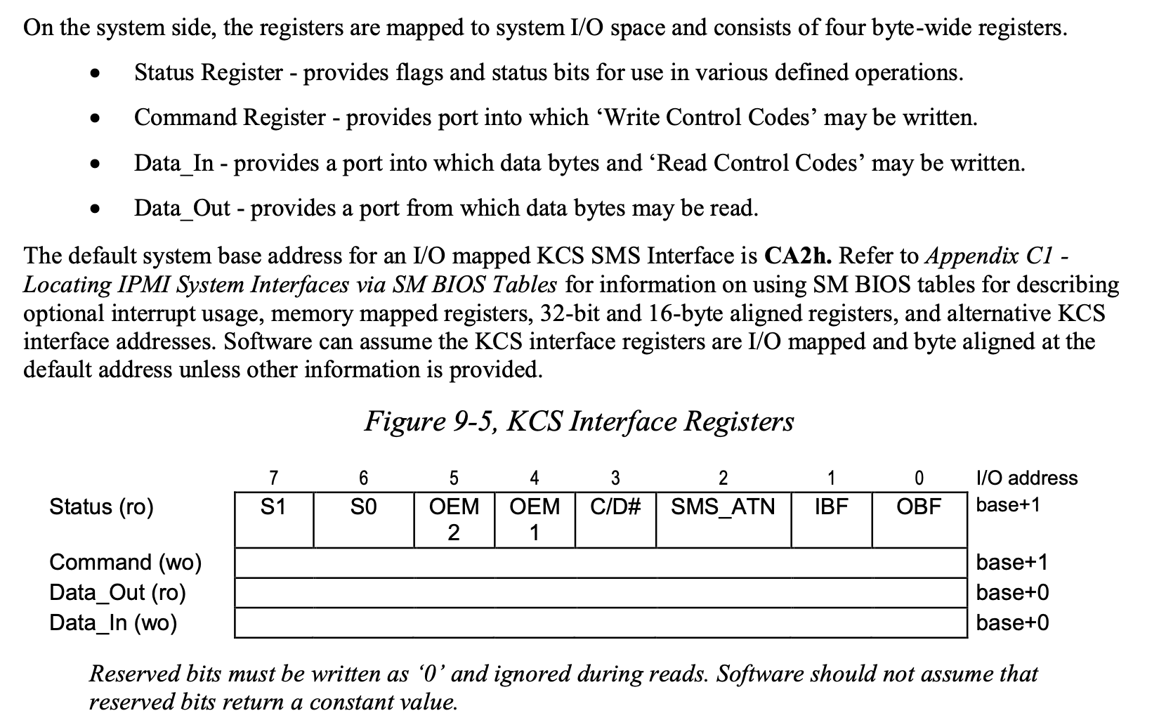
图中的 base 就是上面 ACPI 表记录的 IDTP=0x0CA2,base+1 就是 ACPI 表记录的 ICDP=0x0CA3。结合寄存器的用途,可以猜测 IDTP 是 IPMI Data Transfer Port 的缩写,因为这个 Port 对应的是 Data_In 和 Data_Out;ICDP 是 IPMI Command Data Port 的缩写。
ARM64
再看一个 ARM64 平台上的 IPMI:
Device (IPI0)
{
    Name (_HID, "IPI0001")  // _HID: Hardware ID
    Method (_IFT, 0, NotSerialized)  // _IFT: IPMI Interface Type
    {
        Return (0x03) // BT
    }

    Name (_CRS, ResourceTemplate ()  // _CRS: Current Resource Settings
    {
        QWordMemory (ResourceConsumer, PosDecode, MinFixed, MaxFixed, Cacheable, ReadWrite,
            0x0000000000000000, // Granularity
            0x00000003F00000E4, // Range Minimum
            0x00000003F00000E7, // Range Maximum
            0x0000000000000000, // Translation Offset
            0x0000000000000004, // Length
            ,, , AddressRangeMemory, TypeStatic)
        Interrupt (ResourceConsumer, Level, ActiveHigh, Shared, ,, )
        {
            0x000001E4,
        }
    })
}
这里的 _IFT 返回值是 0x3,查阅文档可知这表示的是 BT 类型。_CRS 中使用了 QWordMemory 宏来描述地址空间,这里实际上就是表示内存地址 0x3F00000E4-0x3F00000E7。
IO APIC
在 DSDT 中,可以找到 IO APIC 的基地址:
Device (APIC)
{
    Name (_HID, EisaId ("PNP0003") /* IO-APIC Interrupt Controller */)  // _HID: Hardware ID
    Name (_CRS, ResourceTemplate ()  // _CRS: Current Resource Settings
    {
        Memory32Fixed (ReadOnly,
            0xFEC00000,         // Address Base
            0x00100000,         // Address Length
            )
    })
}
可以看到 IO APIC 基地址是 0xFEC00000,在网上也可以查到同样的结果。实际上,在 Multiple APIC Description Table (MADT) 中也可以找到 IO APIC 的基地址:
[1ECh 0492   1]                Subtable Type : 01 [I/O APIC]
[1EDh 0493   1]                       Length : 0C
[1EEh 0494   1]                  I/O Apic ID : 08
[1EFh 0495   1]                     Reserved : 00
[1F0h 0496   4]                      Address : FEC00000
[1F4h 0500   4]                    Interrupt : 00000000

[1F8h 0504   1]                Subtable Type : 01 [I/O APIC]
[1F9h 0505   1]                       Length : 0C
[1FAh 0506   1]                  I/O Apic ID : 09
[1FBh 0507   1]                     Reserved : 00
[1FCh 0508   4]                      Address : FEC01000
[200h 0512   4]                    Interrupt : 00000018

[204h 0516   1]                Subtable Type : 01 [I/O APIC]
[205h 0517   1]                       Length : 0C
[206h 0518   1]                  I/O Apic ID : 0A
[207h 0519   1]                     Reserved : 00
[208h 0520   4]                      Address : FEC08000
[20Ch 0524   4]                    Interrupt : 00000020

[210h 0528   1]                Subtable Type : 01 [I/O APIC]
[211h 0529   1]                       Length : 0C
[212h 0530   1]                  I/O Apic ID : 0B
[213h 0531   1]                     Reserved : 00
[214h 0532   4]                      Address : FEC10000
[218h 0536   4]                    Interrupt : 00000028

[21Ch 0540   1]                Subtable Type : 01 [I/O APIC]
[21Dh 0541   1]                       Length : 0C
[21Eh 0542   1]                  I/O Apic ID : 0C
[21Fh 0543   1]                     Reserved : 00
[220h 0544   4]                      Address : FEC18000
[224h 0548   4]                    Interrupt : 00000030
DMA
继续搜索 _HID,还可以找到一些传统的设备,比如 DMA Controller:
// DMA Controller
Device (DMAC)
{
    Name (_HID, EisaId ("PNP0200") /* PC-class DMA Controller */)  // _HID: Hardware ID
    Name (_CRS, ResourceTemplate ()  // _CRS: Current Resource Settings
    {
        IO (Decode16,
            0x0000,             // Range Minimum
            0x0000,             // Range Maximum
            0x00,               // Alignment
            0x10,               // Length
            )
        IO (Decode16,
            0x0081,             // Range Minimum
            0x0081,             // Range Maximum
            0x00,               // Alignment
            0x03,               // Length
            )
        IO (Decode16,
            0x0087,             // Range Minimum
            0x0087,             // Range Maximum
            0x00,               // Alignment
            0x01,               // Length
            )
        IO (Decode16,
            0x0089,             // Range Minimum
            0x0089,             // Range Maximum
            0x00,               // Alignment
            0x03,               // Length
            )
        IO (Decode16,
            0x008F,             // Range Minimum
            0x008F,             // Range Maximum
            0x00,               // Alignment
            0x01,               // Length
            )
        IO (Decode16,
            0x00C0,             // Range Minimum
            0x00C0,             // Range Maximum
            0x00,               // Alignment
            0x20,               // Length
            )
        DMA (Compatibility, NotBusMaster, Transfer8, )
            {4}
    })
}
可以看到,它定义了如下的 IO Port 范围:
0x00-0x0F- 0x81, 0x87, 0x89, 0x8F
0xC0-0xDE
寄存器定义可以在 ISA DMA - OSDev 处找到。
CMOS/RTC
经典的 CMOS/RTC 的 IO 端口定义也可以找到:
Device (RTC)
{
    Name (_HID, EisaId ("PNP0B00") /* AT Real-Time Clock */)  // _HID: Hardware ID
    Name (_CRS, ResourceTemplate ()  // _CRS: Current Resource Settings
    {
        IO (Decode16,
            0x0070,             // Range Minimum
            0x0070,             // Range Maximum
            0x01,               // Alignment
            0x02,               // Length
            )
        IO (Decode16,
            0x0074,             // Range Minimum
            0x0074,             // Range Maximum
            0x01,               // Alignment
            0x04,               // Length
            )
        IRQNoFlags ()
            {8}
    })
    Method (_STA, 0, NotSerialized)  // _STA: Status
    {
        If ((STAS == 0x01))
        {
            Return (0x0F)
        }
        Else
        {
            Return (0x00)
        }
    }
}
可以看到,它的 IO Port 是 0x70-0x71 和 0x74-0x78,中断号 8,和 CMOS - OSDev 是一致的。
启动图片
启动图片以 BMP 格式保存在内存中,基地址记录在 BGRT 表中。可以直接从 /sys/firmware/acpi/bgrt/image 获取启动的图片内容。
PCIe
Root Bridge
PCIe 总线是自带枚举功能的,所以只需要找到 Root Bridge,其他设备都可以枚举出来。而 ACPI 就提供了寻找 Root Bridge 的方法。
搜索 PNP0A08 可以找到 PCIe 总线:
// PCIe Bus 00
Device (PC00)
{
    Name (_HID, EisaId ("PNP0A08") /* PCI Express Bus */)  // _HID: Hardware ID
    Name (_CID, EisaId ("PNP0A03") /* PCI Bus */)  // _CID: Compatible ID

    Name (P0RS, ResourceTemplate ()
    {
        WordBusNumber (ResourceProducer, MinFixed, MaxFixed, PosDecode,
            0x0000,             // Granularity
            0x0000,             // Range Minimum
            0x0015,             // Range Maximum
            0x0000,             // Translation Offset
            0x0016,             // Length
            ,, )
        IO (Decode16,
            0x0CF8,             // Range Minimum
            0x0CF8,             // Range Maximum
            0x01,               // Alignment
            0x08,               // Length
            )
        WordIO (ResourceProducer, MinFixed, MaxFixed, PosDecode, EntireRange,
            0x0000,             // Granularity
            0x0000,             // Range Minimum
            0x0CF7,             // Range Maximum
            0x0000,             // Translation Offset
            0x0CF8,             // Length
            ,, , TypeStatic, DenseTranslation)
        WordIO (ResourceProducer, MinFixed, MaxFixed, PosDecode, EntireRange,
            0x0000,             // Granularity
            0x1000,             // Range Minimum
            0x57FF,             // Range Maximum
            0x0000,             // Translation Offset
            0x4800,             // Length
            ,, , TypeStatic, DenseTranslation)
        DWordMemory (ResourceProducer, PosDecode, MinFixed, MaxFixed, Cacheable, ReadWrite,
            0x00000000,         // Granularity
            0x000A0000,         // Range Minimum
            0x000BFFFF,         // Range Maximum
            0x00000000,         // Translation Offset
            0x00020000,         // Length
            ,, , AddressRangeMemory, TypeStatic)
        DWordMemory (ResourceProducer, PosDecode, MinFixed, MaxFixed, Cacheable, ReadWrite,
            0x00000000,         // Granularity
            0x00000000,         // Range Minimum
            0x00000000,         // Range Maximum
            0x00000000,         // Translation Offset
            0x00000000,         // Length
            ,, _Y00, AddressRangeMemory, TypeStatic)
        DWordMemory (ResourceProducer, PosDecode, MinFixed, MaxFixed, NonCacheable, ReadWrite,
            0x00000000,         // Granularity
            0xFE010000,         // Range Minimum
            0xFE010FFF,         // Range Maximum
            0x00000000,         // Translation Offset
            0x00001000,         // Length
            ,, , AddressRangeMemory, TypeStatic)
        DWordMemory (ResourceProducer, PosDecode, MinFixed, MaxFixed, NonCacheable, ReadWrite,
            0x00000000,         // Granularity
            0xFD000000,         // Range Minimum
            0xFE7FFFFF,         // Range Maximum
            0x00000000,         // Translation Offset
            0x01800000,         // Length
            ,, , AddressRangeMemory, TypeStatic)
        DWordMemory (ResourceProducer, PosDecode, MinFixed, MaxFixed, NonCacheable, ReadWrite,
            0x00000000,         // Granularity
            0x70000000,         // Range Minimum
            0x92FFFFFF,         // Range Maximum
            0x00000000,         // Translation Offset
            0x23000000,         // Length
            ,, , AddressRangeMemory, TypeStatic)
        QWordMemory (ResourceProducer, PosDecode, MinFixed, MaxFixed, NonCacheable, ReadWrite,
            0x0000000000000000, // Granularity
            0x0000000000000000, // Range Minimum
            0x0000000000000000, // Range Maximum
            0x0000000000000000, // Translation Offset
            0x0000000000000000, // Length
            ,, , AddressRangeMemory, TypeStatic)
    })

    Method (_CRS, 0, NotSerialized)  // _CRS: Current Resource Settings
    {
        EROM ()
        Return (P0RS) /* \_SB_.PC00.P0RS */
    }
}
上面省略掉了很多内容,只保留了 Root Bridge 的资源 _CRS,这部分内容和 Linux 的 dmesg 是一致的:
ACPI: PCI Root Bridge [PC00] (domain 0000 [bus 00-15])
acpi PNP0A08:00: _OSC: OS supports [ExtendedConfig ASPM ClockPM Segments MSI]
acpi PNP0A08:00: _OSC: platform does not support [SHPCHotplug AER LTR]
acpi PNP0A08:00: _OSC: OS now controls [PCIeHotplug PME PCIeCapability]
acpi PNP0A08:00: host bridge window expanded to [mem 0xfd000000-0xfe7fffff window]; [mem 0xfd000000-0xfe7fffff window] ignored
PCI host bridge to bus 0000:00
pci_bus 0000:00: root bus resource [io  0x0000-0x0cf7 window]
pci_bus 0000:00: root bus resource [io  0x1000-0x57ff window]
pci_bus 0000:00: root bus resource [mem 0x000a0000-0x000bffff window]
pci_bus 0000:00: root bus resource [mem 0x000c4000-0x000c7fff window]
pci_bus 0000:00: root bus resource [mem 0xfd000000-0xfe7fffff window]
pci_bus 0000:00: root bus resource [mem 0x70000000-0x92ffffff window]
pci_bus 0000:00: root bus resource [bus 00-15]
Linux 相关代码在 acpi_pci_root_create 函数中:
struct pci_bus *acpi_pci_root_create(struct acpi_pci_root *root,
                     struct acpi_pci_root_ops *ops,
                     struct acpi_pci_root_info *info,
                     void *sysdata)
{
    // omitted
    ret = acpi_pci_probe_root_resources(info);
    // omitted
    pci_acpi_root_add_resources(info);
    pci_add_resource(&info->resources, &root->secondary);
    bus = pci_create_root_bus(NULL, busnum, ops->pci_ops,
                  sysdata, &info->resources);
}
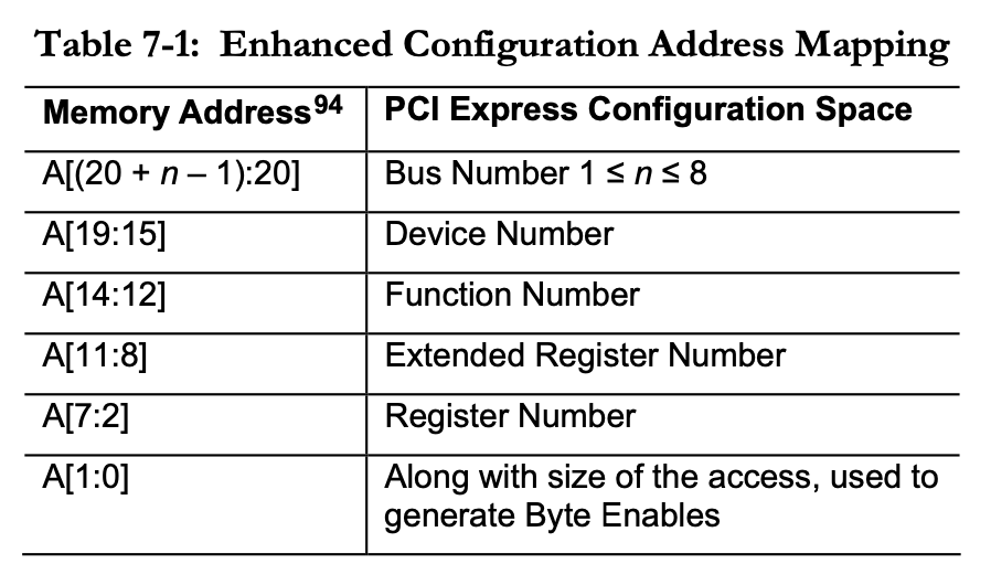
MCFG
除了上面的 Root Bridge 以外,还有一个很重要的问题是,如何访问 PCIe 的 Configuration Space。传统的办法是通过 IO Port 0xCF8 和 0xCFC,但是这个方法慢,并且有局限性。而较新的办法是 Enhanced Configuration Access Mechanism (ECAM),把 PCIe 设备的 Configuration Space 映射到内存中,那么就需要一个基地址。这个基地址是在 MCFG 表中给出的:
[02Ch 0044   8]                 Base Address : 0000000060000000
[034h 0052   2]         Segment Group Number : 0000
[036h 0054   1]             Start Bus Number : 00
[037h 0055   1]               End Bus Number : FF
[038h 0056   4]                     Reserved : 00000000
内核输出:
PCI: MMCONFIG for domain 0000 [bus 00-ff] at [mem 0x60000000-0x6fffffff] (base 0x60000000)
PCI: MMCONFIG at [mem 0x60000000-0x6fffffff] reserved in E820
有了这个信息以后,就可以计算出要访问 Configuration Space 时 MMIO 的地址了:
相关文档
Linux 的文档 ACPI considerations for PCI host bridges 对 ACPI PCIe 描述的比较详细,摘录如下:
The general rule is that the ACPI namespace should describe everything the
OS might use unless there’s another way for the OS to find it [1, 2].

For example, there’s no standard hardware mechanism for enumerating PCI host
bridges, so the ACPI namespace must describe each host bridge, the method
for accessing PCI config space below it, the address space windows the host
bridge forwards to PCI (using _CRS), and the routing of legacy INTx
interrupts (using _PRT).

PCI devices, which are below the host bridge, generally do not need to be
described via ACPI. The OS can discover them via the standard PCI
enumeration mechanism, using config accesses to discover and identify
devices and read and size their BARs. However, ACPI may describe PCI devices
if it provides power management or hotplug functionality for them or if the
device has INTx interrupts connected by platform interrupt controllers and a
_PRT is needed to describe those connections.
文档和上面讲的是一致的,对于 PCIe 自己可以枚举出来的,ACPI 就不需要再重复;但是枚举需要首先知道有哪些 Root Bridge 以及 ECAM 的基地址,这个信息只能由 ACPI 来提供。
The PCIe spec requires the Enhanced Configuration Access Method (ECAM)
unless there’s a standard firmware interface for config access, e.g., the
ia64 SAL interface [7]. A host bridge consumes ECAM memory address space and
converts memory accesses into PCI configuration accesses. The spec defines
the ECAM address space layout and functionality; only the base of the
address space is device-specific. An ACPI OS learns the base address from
either the static MCFG table or a _CBA method in the PNP0A03 device.
这一段讲的其实就是 ECAM 与 MCFG 的关系。
PCIe 设备
虽然有了 Root Bridge 以后,PCIe 总线下的设备都可以枚举出来,但是 ACPI 表中也可以记录 PCIe 设备,可以提供更多信息,例如 Power State 等等。具体来说,只需要在 Root Bridge 的结点下继续增加 Device 就可以了:
Scope (_SB)
{
    Device (PC00)
    {
        // 00:00.0 DMI3 Registers
        Device (DMI0)
        {
            Name (_ADR, 0x00)  // _ADR: Address
        }

        // 00:04.0 CBDMA Registers
        Device (CB0A)
        {
            Name (_ADR, 0x00040000)  // _ADR: Address
        }

        Device (CB0B)
        {
            Name (_ADR, 0x00040001)  // _ADR: Address
        }

        // 00:05.0 MM/Vt-d Configuration Registers
        Device (IIM0)
        {
            Name (_ADR, 0x00050000)  // _ADR: Address
        }

        // 00:08.0 Ubox Registers
        Device (UBX0)
        {
            Name (_ADR, 0x00080000)  // _ADR: Address
        }

        Device (ALZA)
        {
            Name (_ADR, 0x000E0000)  // _ADR: Address
        }

        Device (DISP)
        {
            Name (_ADR, 0x000F0000)  // _ADR: Address
        }

        Device (IHC1)
        {
            Name (_ADR, 0x00100000)  // _ADR: Address
        }

        Device (IHC2)
        {
            Name (_ADR, 0x00100001)  // _ADR: Address
        }

        Device (IIDR)
        {
            Name (_ADR, 0x00100002)  // _ADR: Address
        }

        Device (IMKT)
        {
            Name (_ADR, 0x00100003)  // _ADR: Address
        }

        Device (IHC3)
        {
            Name (_ADR, 0x00100004)  // _ADR: Address
        }

        Device (MRO0)
        {
            Name (_ADR, 0x00110000)  // _ADR: Address
        }

        Device (MRO1)
        {
            Name (_ADR, 0x00110001)  // _ADR: Address
        }

        // 00:14.0 USB 3.0 xHCI Controller
        Device (XHCI)
        {
            Name (_ADR, 0x00140000)  // _ADR: Address
        }

        Device (OTG0)
        {
            Name (_ADR, 0x00140001)  // _ADR: Address
        }

        // 00:14.2 PCH Thermal Subsystem
        Device (TERM)
        {
            Name (_ADR, 0x00140002)  // _ADR: Address
        }

        Device (CAMR)
        {
            Name (_ADR, 0x00140003)  // _ADR: Address
        }

        Device (NTHP)
        {
            Name (_ADR, 0x00140004)  // _ADR: Address
        }

        // 00:16.0 PCH CSME HECI #1
        Device (HEC1)
        {
            Name (_ADR, 0x00160000)  // _ADR: Address
        }

        Device (HEC2)
        {
            Name (_ADR, 0x00160001)  // _ADR: Address
        }

        Device (IDER)
        {
            Name (_ADR, 0x00160002)  // _ADR: Address
        }

        Device (MEKT)
        {
            Name (_ADR, 0x00160003)  // _ADR: Address
        }

        Device (HEC3)
        {
            Name (_ADR, 0x00160004)  // _ADR: Address
        }

        Device (NAN1)
        {
            Name (_ADR, 0x00180000)  // _ADR: Address
        }
    }
}
这里的 _ADR 编码了设备的 Device 和 Function,ACPI 标准 Table 6.2 定义:高 word 表示 Device,低 word 表示 Function。所以上面的 DMI0 就是 Device=0, Function=0,CB0A 就是 Device=4, Function=0,CB0B 就是 Device=4, Function=1。这些与 lspci 的输出基本是一致的,有一些设备没有出现,可能和具体的 CPU 型号有关:
00:00.0 Host bridge: Intel Corporation Sky Lake-E DMI3 Registers (rev 07)
00:04.0 System peripheral: Intel Corporation Sky Lake-E CBDMA Registers (rev 07)
00:04.1 System peripheral: Intel Corporation Sky Lake-E CBDMA Registers (rev 07)
00:04.2 System peripheral: Intel Corporation Sky Lake-E CBDMA Registers (rev 07)
00:04.3 System peripheral: Intel Corporation Sky Lake-E CBDMA Registers (rev 07)
00:04.4 System peripheral: Intel Corporation Sky Lake-E CBDMA Registers (rev 07)
00:04.5 System peripheral: Intel Corporation Sky Lake-E CBDMA Registers (rev 07)
00:04.6 System peripheral: Intel Corporation Sky Lake-E CBDMA Registers (rev 07)
00:04.7 System peripheral: Intel Corporation Sky Lake-E CBDMA Registers (rev 07)
00:05.0 System peripheral: Intel Corporation Sky Lake-E MM/Vt-d Configuration Registers (rev 07)
00:05.2 System peripheral: Intel Corporation Sky Lake-E RAS (rev 07)
00:05.4 PIC: Intel Corporation Sky Lake-E IOAPIC (rev 07)
00:08.0 System peripheral: Intel Corporation Sky Lake-E Ubox Registers (rev 07)
00:08.1 Performance counters: Intel Corporation Sky Lake-E Ubox Registers (rev 07)
00:08.2 System peripheral: Intel Corporation Sky Lake-E Ubox Registers (rev 07)
00:14.0 USB controller: Intel Corporation 200 Series/Z370 Chipset Family USB 3.0 xHCI Controller
00:14.2 Signal processing controller: Intel Corporation 200 Series PCH Thermal Subsystem
00:16.0 Communication controller: Intel Corporation 200 Series PCH CSME HECI #1
00:17.0 SATA controller: Intel Corporation 200 Series PCH SATA controller [AHCI mode]
前面提到的一些传统的设备,比如 DMA Controller,RTC 等,其实就是在 PCIe 下的 ISA bridge 下声明的:
Scope (_SB)
{
    Device (PC00)
    {
        // 00:1f.0 ISA bridge: Intel Corporation X299 Chipset LPC/eSPI Controller
        Device (LPC0)
        {
            Name (_ADR, 0x001F0000)  // _ADR: Address

            Device (DMAC)
            {
                Name (_HID, EisaId ("PNP0200") /* PC-class DMA Controller */)  // _HID: Hardware ID
            }

            Device (RTC)
            {
                Name (_HID, EisaId ("PNP0B00") /* AT Real-Time Clock */)  // _HID: Hardware ID
            }

            Device (PIC)
            {
                Name (_HID, EisaId ("PNP0000") /* 8259-compatible Programmable Interrupt Controller */)  // _HID: Hardware ID
            }

            Device (FPU)
            {
                Name (_HID, EisaId ("PNP0C04") /* x87-compatible Floating Point Processing Unit */)  // _HID: Hardware ID
            }

            Device (TMR)
            {
                Name (_HID, EisaId ("PNP0100") /* PC-class System Timer */)  // _HID: Hardware ID
            }

            Device (HPET)
            {
                Name (_HID, EisaId ("PNP0103") /* HPET System Timer */)  // _HID: Hardware ID
            }

            // omitted
        }
    }
}
修改 ACPI 表内容
想要修改 ACPI 表内容,最根本的办法是修改固件,但是修改起来比较麻烦。Linux 提供了一些方法来运行时打补丁:
- Upgrading ACPI tables via initrd:覆盖 ACPI 表
- SSDT Overlays:添加额外的 SSDT 表,类似 DT Overlay
在黑苹果中,一般则是在 Bootloader(Clover/OpenCore) 一步把 ACPI 表修改了,如 How to Patch Laptop DSDT and SSDTs。
ACPI 硬件规范
除了用来描述系统中已有的设备,ACPI 还对硬件做出了一些要求,在标准的 Chapter 4 ACPI Hardware Specification 中定义。例如,电源按钮是如何通知操作系统的?操作系统的重启和关机是怎么实现的?
电源按钮
首先来看电源按钮(Power Button)。在 ACPI 中,定义了两种 Power Button 的实现方法,第一种就是比较经典的硬件按钮 + 中断的模式,当按下按钮的时候,中断状态(PWRBTN_STS)拉高,如果此时中断使能(PWRBTN_EN)也为高,就触发中断。这时候操作系统就知道电源键被按下了,开始进行关机操作。
第二种实现方法则利用了 ACPI 的可编程性。具体来说,当按下电源键的时候,操作系统会收到一个 SCI(System Control Interrupt),此时操作系统会根据中断编号,去执行 ACPI 中的函数,函数去读取当前的电源键状态,然后调用 Notify 函数来通知操作系统,电源键被按下了。
在使用虚拟机的时候,会知道 ACPI Shutdown 的说法,其实就是模拟了按下电源键的行为。QEMU 的相关代码:
void acpi_pm1_evt_power_down(ACPIREGS *ar)
{
    if (ar->pm1.evt.en & ACPI_BITMASK_POWER_BUTTON_ENABLE) {
        ar->pm1.evt.sts |= ACPI_BITMASK_POWER_BUTTON_STATUS;
        ar->tmr.update_sci(ar);
    }
}
这个函数模拟了电源按钮,如果 PWRBTN_EN=1,就设置 PWRBTN_STS=1 并发送 SCI 中断。
那么,操作系统如何访问 PWRBTN_EN 和 PWRBTN_STS 呢?在 FADP(Fixed ACPI Descrption Table) 表中,可以找到 PM1A/B Event Block Address 和 PM1A/B Control Block Address:
[038h 0056   4]     PM1A Event Block Address : 0000B000
[03Ch 0060   4]     PM1B Event Block Address : 00000000
[040h 0064   4]   PM1A Control Block Address : 0000B004
[044h 0068   4]   PM1B Control Block Address : 00000000

[058h 0088   1]       PM1 Event Block Length : 04
[059h 0089   1]     PM1 Control Block Length : 02
那么就可以通过 IO Port 来访问这些寄存器了。PWNBTN_STS 属于 PM1 Status Registers,地址是 PM1A/B Event Block Address=0xB000;PWNBTN_EN 属于 PM1 Enable Registers,地址是 PM1A/B Event Block Register + PM1 Event Block Length / 2=0xB002。
这里的 PM1A/B 是 Register Grouping,使得硬件上可以把寄存器实现在两个不同的芯片上,分别实现一部分功能。操作系统读取的时候,要读取 A 和 B 然后 OR 起来,写入的时候则是 A 和 B 都要写。像上面的情况,就是只有 A 没有 B,那就直接读写 A 就可以了。
关机
另一方面,如果 OS 想要关机,那要怎么告诉硬件呢?还是通过 ACPI。在 PM1 Control Registers 中,可以通过写入 SLP_TYPx 和 SLP_EN 字段来进行休眠或者关机操作。
下面是 QEMU 针对 SLP_EN 写入的处理代码:
/* ACPI PM1aCNT */
static void acpi_pm1_cnt_write(ACPIREGS *ar, uint16_t val)
{
    ar->pm1.cnt.cnt = val & ~(ACPI_BITMASK_SLEEP_ENABLE);

    if (val & ACPI_BITMASK_SLEEP_ENABLE) {
        /* change suspend type */
        uint16_t sus_typ = (val >> 10) & 7;
        switch (sus_typ) {
        case 0: /* soft power off */
            qemu_system_shutdown_request(SHUTDOWN_CAUSE_GUEST_SHUTDOWN);
            break;
        case 1:
            qemu_system_suspend_request();
            break;
        default:
            if (sus_typ == ar->pm1.cnt.s4_val) { /* S4 request */
                qapi_event_send_suspend_disk();
                qemu_system_shutdown_request(SHUTDOWN_CAUSE_GUEST_SHUTDOWN);
            }
            break;
        }
    }
}
PM Timer
ACPI 还提供了一个 3.579545 MHz 的时钟 PM_TMR。QEMU 相关代码:
/* PM Timer ticks per second (HZ) */
#define PM_TIMER_FREQUENCY  3579545

static inline int64_t acpi_pm_tmr_get_clock(void)
{
    return muldiv64(qemu_clock_get_ns(QEMU_CLOCK_VIRTUAL), PM_TIMER_FREQUENCY,
                    NANOSECONDS_PER_SECOND);
}
Linux 也可以把它当成一个时钟源:
相关代码:
/*
 * The I/O port the PMTMR resides at.
 * The location is detected during setup_arch(),
 * in arch/i386/kernel/acpi/boot.c
 */
u32 pmtmr_ioport __read_mostly;

static inline u32 read_pmtmr(void)
{
    /* mask the output to 24 bits */
    return inl(pmtmr_ioport) & ACPI_PM_MASK;
}

static u64 acpi_pm_read(struct clocksource *cs)
{
    return (u64)read_pmtmr();
}

static struct clocksource clocksource_acpi_pm = {
    .name       = "acpi_pm",
    .rating     = 200,
    .read       = acpi_pm_read,
    .mask       = (u64)ACPI_PM_MASK,
    .flags      = CLOCK_SOURCE_IS_CONTINUOUS,
};

/* Number of PMTMR ticks expected during calibration run */
#define PMTMR_TICKS_PER_SEC 3579545

static int __init init_acpi_pm_clocksource(void)
{
    // omitted
    return clocksource_register_hz(&clocksource_acpi_pm,
                        PMTMR_TICKS_PER_SEC);
}
GPE
除了上面 PM1 中提到的一些中断来源,ACPI 还提供了通用的 General Purpose Event,硬件可以自定义一些中断编号,依然是通过 SCI 中断通知操作系统,操作系统根据 GPE 的 STS 寄存器来判断哪个 GPE 触发了中断,然后执行对应的 ACPI 函数。GPE 的地址也是在 FADT 中提供:
在 DSDT 的 \_GPE 下面,可以定义函数,在 GPE 到达的时候,会被操作系统执行。格式是 \_GPE._Exx 或 \_GPE._Lxx,E 表示 Edge sensitive,L 表示 Level sensitive。例如操作系统判断收到了 GPE 4,那可能会执行 \_GPE._L04 或 \_GPE._E04 函数。
PCIe Hot Plug
在 QEMU 中,如果虚拟机要进行 PCIe Hot Plug 的时候,例如要增加 PCIe 设备,或者删除已有的 PCIe 设备,需要设法通知操作系统,告知操作系统哪个地方有新的设备,或者哪个已有的设备被弹出。QEMU 的实现文档是QEMU<->ACPI BIOS PCI hotplug interface,这里结合代码来解释一下。
在 QEMU 中,要插入一个新的 PCIe 设备的时候,按照设备的 bus 和 slot 设置位为 1,并且发送 GPE:
void acpi_pcihp_device_plug_cb(HotplugHandler *hotplug_dev, AcpiPciHpState *s,
                               DeviceState *dev, Error **errp)
{
    // omitted

    bsel = acpi_pcihp_get_bsel(bus);
    g_assert(bsel >= 0);
    s->acpi_pcihp_pci_status[bsel].up |= (1U << slot);
    acpi_send_event(DEVICE(hotplug_dev), ACPI_PCI_HOTPLUG_STATUS);
}

// acpi_send_event eventually calls piix4_send_gpe
static void piix4_send_gpe(AcpiDeviceIf *adev, AcpiEventStatusBits ev)
{
    PIIX4PMState *s = PIIX4_PM(adev);

    acpi_send_gpe_event(&s->ar, s->irq, ev);
}

void acpi_send_gpe_event(ACPIREGS *ar, qemu_irq irq,
                         AcpiEventStatusBits status)
{
    ar->gpe.sts[0] |= status;
    acpi_update_sci(ar, irq);
}
查看头文件,可知 ACPI_PCI_HOTPLUG_STATUS=2,根据上面的代码,可知这实际上就是发送了 GPE1。操作系统会执行 \_GPE._E01 函数:
Scope (_GPE)
{
    Name (_HID, "ACPI0006" /* GPE Block Device */)  // _HID: Hardware ID
    Method (_E01, 0, NotSerialized)  // _Exx: Edge-Triggered GPE, xx=0x00-0xFF
    {
        Acquire (\_SB.PCI0.BLCK, 0xFFFF)
        \_SB.PCI0.PCNT () // PCIe Notify
        Release (\_SB.PCI0.BLCK)
    }
}
这个代码上了锁,然后调用 \_SB.PCI0.PCNT 函数,PCNT 函数定义如下:
// PCIe Status
OperationRegion (PCST, SystemIO, 0xAE00, 0x08)
Field (PCST, DWordAcc, NoLock, WriteAsZeros)
{
    PCIU,   32, // Up
    PCID,   32  // Down
}

// PCIe Notify
Method (PCNT, 0, NotSerialized)
{
    BNUM = Zero // Bus Num = 0
    DVNT (PCIU, One) // Device Notify
    DVNT (PCID, 0x03) // Device Notify
}
上面的代码中,PCIU 的意思是 PCIe Up,就是新出现的设备;PCID 的意思是 PCIe Down,就是要删除的设备。PCIU 和 PCID 都要通过 IO Port 访问,根据上面的 OperationRegion 可知 PCIU=0xAE00,PCID=0xAE04。你可能已经猜到了 PCIU 和 PCID 的实现:当 CPU 读取这两个 IO Port 的时候,就会返回前面 acpi_pcihp_device_plug_cb 函数写入的 acpi_pcihp_pci_status 数组:
static uint64_t pci_read(void *opaque, hwaddr addr, unsigned int size)
{
    // omitted
    switch (addr) {
    case PCI_UP_BASE:
        val = s->acpi_pcihp_pci_status[bsel].up;
        if (!s->legacy_piix) {
            s->acpi_pcihp_pci_status[bsel].up = 0;
        }
        trace_acpi_pci_up_read(val);
        break;
    case PCI_DOWN_BASE:
        val = s->acpi_pcihp_pci_status[bsel].down;
        trace_acpi_pci_down_read(val);
        break;
    }
    // omitted
}
因此在 PCNT 函数中,读取 PCIU 和 PCID 就可以知道一个 Bitmap,记录了哪些设备出现了变化。最后一步就是通知操作系统了。在 ACPI 中,可以调用 Notify 函数,用于通知操作系统,通知的参数见 Table 5.187,这里列出来前面几种:
- 0: Bus Check, This notification is performed on a device object to indicate to OSPM that it needs to perform a Plug and Play re-enumeration operation on the device tree starting from the point where it has been notified
- 1: Device Check, Used to notify OSPM that the device either appeared or disappeared. If the device has appeared, OSPM will re-enumerate from the parent.
- 2: Device Wake, Used to notify OSPM that the device has signaled its wake event, and that OSPM needs to notify OSPM native device driver for the device.
- 3: Eject Request, Used to notify OSPM that the device should be ejected, and that OSPM needs to perform the Plug and Play ejection operation.
PCNT 函数调用 DVNT 函数来进行最终的 Notify,对于 PCI Up,需要发送 1(Device Check) 让操作系统新的设备出现;对于 PCI Down,需要发送 3(Eject Request) 让操作系统弹出设备。这就解释了 PCNT 为什么要这样实现:
// PCIe Notify
Method (PCNT, 0, NotSerialized)
{
    BNUM = Zero // Bus Num = 0
    DVNT (PCIU, One) // Device Notify(1=Device Check)
    DVNT (PCID, 0x03) // Device Notify(3=Eject Request)
}
DVNT 的实现方法很粗暴,就是检查各个位,然后发送 Notify 到相应的 PCIe Slot 上:
// Device Notify
Method (DVNT, 2, NotSerialized)
{
    If ((Arg0 & 0x08))
    {
        Notify (S18, Arg1)
    }

    If ((Arg0 & 0x10))
    {
        Notify (S20, Arg1)
    }

    If ((Arg0 & 0x20))
    {
        Notify (S28, Arg1)
    }
    // omitted
}
这样就完成了整个 PCIe Hot Plug 的过程。回顾一下:
- QEMU 要进行 PCIe Hot Plug
- QEMU 记录要 Hot Plug 设备到数组中
- QEMU 发送 GPE
- OS 执行 GPE 1 Handler
- Handler 读取 PCIU/PCID,根据 Bitmap 去 Notify
- OS 根据 Notify 的设备进行对应的操作
可以看到,大部分的工作其实是 QEMU 完成的,OS 只需要在收到 SCI 的时候,判断是 GPE 1 事件,执行对应的处理函数,等待 Notify 的到来。
Power State
ACPI 定义的 Power State:
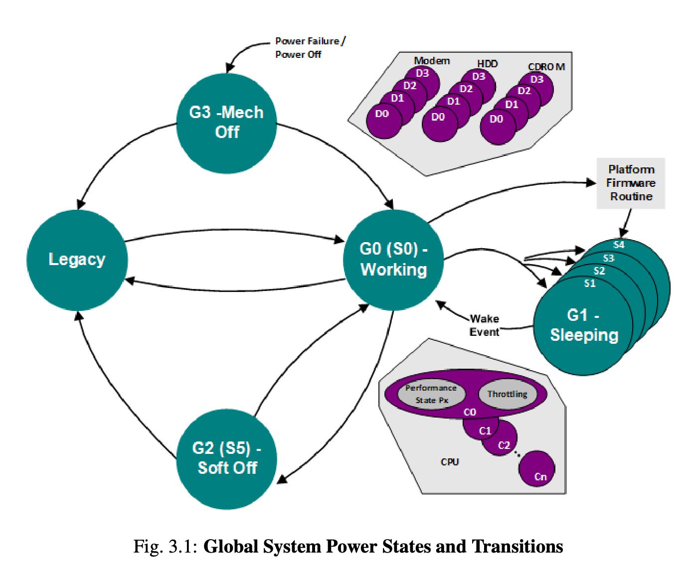
- G0-G3: 全局状态,G0 表示正在工作
- S0-S5:睡眠状态,S0 表示正在工作,S5 表示关机
- D0-D3:设备状态
- C0-Cn:CPU 状态